Typical Smart-Arm Strategy
Logic Control is needed for interface and data management between the ETA smart-arm encoders and the DC Tool controller (supplied by others). This PLC or PC program reads the encoder values and the tool controller I/O and coordinates and supervises an error proofing strategy for human operators to make the product efficiently and without defects.
ETA does not offer PLC or PC controls or hardware for our smart-arms. We manufacture quality smart torque arms with on board encoders and sensors for our customers to integrate with their intelligent assembly tools or even simple air powered tools in some cases. Most customers write their own logic for their PLC or PC already specified for that cell or station. Our ETA distributors may have resources to help you with control interface, if you need it. We can make the introductions if you want to look into purchasing controls from others.
ETA also has a number of customers using our Smart-Arms to routinely repair product that is initially assembled by robots. On some labor intensive assemblies, the robotics saves labor cost even if it randomly has a small percentage of fastener misfires. In these cases, the nature of the product is such that human repair of errors created by the robotic system is inevitable. The customer’s engineers write the PLC programming to record the fastener location(s) from the smart-arm’s encoders and torque data from the tool controller. This data documents the repair procedure per serial number to make sure each and every product unit is shipped 100% defect free.
Standard New Part Assembly Strategy
1: Programming code is written so that fastener location and sequence (if fasteners must be tightened in a specific order) is “taught” while the operator interface is in “Assembly Set-Up Mode”. This is done by positioning the arm on each fastener on an actual part(s) and “setting” or recording encoder values in the PLC for each position. A teach mode for new part set-up is universally accepted as the preferred control strategy among smart-arm users. Designing logic to enter fastener coordinates numerically instead of designing a “teach” mode into your smart-arm controls makes component assembly set-up difficult and time consuming.
Note; Depending on your fixture and other factors it might be possible that the Smart-Arm Elbow could be folded to either side, giving different values from both encoders. If this is the case, then the teach mode logic should be written to prompt the set-up person to teach each fastener location approached from both directions so that your program knows that either set of X/Y values is acceptable.
2: In order to effectively use smart-arm strategy for error proofing, consistent positioning of the product from one unit to the next is important. This can be done with fixturing, nesting or parking against stops on a moving assembly line. Also, with regard to threaded fasteners, allowance for the torque reaction’s effect on the product’s stability is needed.
3: Some consideration may also be needed on the target size and tolerance needed for each fastener location on the given assembly. ETA smart-arms are capable of detecting vertical screw locations as close as 1/8” (3mm) apart center to center, provided the tool spindle and driver bit or socket do not have a lot of wiggle. However, if your fastener locations are not close together, the window for each location can be increased in size by programming more tolerance into the encoder values, thereby making the tool enable zone less susceptible to part misalignment.
4: Please note that the actual fastening values and strategy regarding set torque, prevailing torque, angle, spindle speed, forward/ reverse and any other strategy is part of the program on the tool manufacturer’s controller. The PLC should provide Enable and Disable Supervision to the DC Tool controller based on the ETA smart-arm’s encoder values. In most cases the PLC can also change the DC Tool’s torque and angle strategy, etc based on the tool’s location and sequence, as needed. If required, one can also control inputs from a Smart Socket Tray or other external sensors working in conjunction with the smart-arm sensor inputs. Many of our ETA smart-arms support hand-held screw feeder systems and the same PLC that controls the screw feeder controls the smart-arm logic.
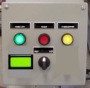
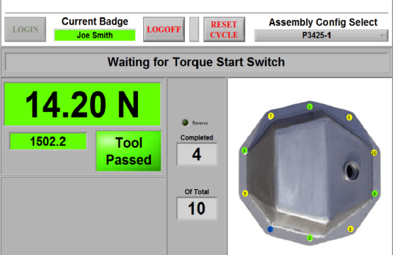
5: If each smart-arm is used for only 1 or a few fasteners, with little or no product variation, most designers opt for a simple “Red Light / Green Light” operator interface. Conversely, if the smart-arm is set up to switch to different product variations or there are a lot of fasteners per assembly, then a graphical User Interface (GUI) is helpful because a photo or image of the assembly can be displayed with fastener locations highlighted and numbered on your monitor image. You can also display other info on the monitor like fastener count, torque of last rundown or whatever is desired. Controls could also be coded to accept bar code scanning, worker ID badge scanning or whatever you need. Also many manufacturers want to store assembly data by individual serial number or product batch number.
6: When a new set-up is completed or recalled from an assembly menu, the tool should be disabled via the I/O on the controller unless the human operator positions the tool directly on or over the first fastener target. Typically the operator interface should acknowledge that the operator has the tool in the correct position. This can be a green light or a screen color change on a GUI.
7: With the correct position acknowledged by the interface, the tool can be enabled via the I/O on the tool’s controller and the tool can be started and the fastener can be driven.
8: Once you get signal from the tool controller that the tool is running, the best practice is to stop monitoring the encoder readings for the balance of that screw’s rundown.
9: If a good torque & angle is achieved, the encoder values can again be monitored by the logic until the arm is moved successfully within the second fastener target location. With location acknowledgment an enable signal is again sent to the tool controller. The encoder values outputted between fastener locations is unimportant.
10: Strategy may be needed to deal with fastener rundowns that fall outside your torque and angle parameters you set in the tool’s controller. Do you want to stop the assembly person from continuing to the next faster location until a passing torque and angle is achieved at the current location? Or do you want to document the failed rundown and move on? Your program should have a strategy for failed rundowns or defective product.
Get in touch with us today
Ergonomic Tool Arms, LLC
P.O. Box 534
Doylestown, PA 18901
Phone: 855 TOOL ARM
Phone: (855) 866-5276
contact@toolarms.com

All rights reserved to SmartArms.com